消息来源csdn,看起来很复杂适合研究院和大公司弄弄~
RoomAlive 利用了 Kinect 与投影仪,将虚拟世界投射到房间的任何地方,并且可以与用户进行互动,该工具包支持创建动态投影映射体验。微软研究所已经使用该工具包好几年,其中用于各式各样的互动投影映射项目,诸如 RoomAlive、 IllumiRoom、 ManoAMano、 Beamatron 以及 Room2Room。
该工具包包含两个独立的项目:
- ProCamCalibration——这个 C# 项目被用来校准室内的多个投影仪和 Kinect 摄像头,并支持沉浸式、动态映射体验。代码库还包含一个使用 Direct3D 开发的简单投影映射示例。
- RoomAlive 工具包且支持 Unity ——支持 Unity 的 RoomAlive 工具包包含一组 Unity 脚本和支持沉浸式和动态投影映射体验的工具,同时基于 ProCamCalibration 的投影相机校准。这个项目还包含一个工具流和渲染 Kinect 深度数据到 Unity。
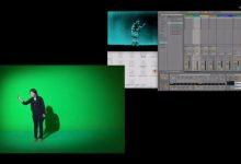
以下是 RoomAlive 项目的一个示例场景(使用 6 台投影机和 6 个 Kinect 相机):

我们进入github看看介绍页面
RoomAlive Toolkit for Unity README
RoomAlive Toolkit for Unity contains is a set of Unity scripts and tools that enable immersive, dynamic projection mapping experiences, based on the projection-camera calibration from RoomAlive Toolkit.
The toolkit can be used to:
- Bring Kinect depth and color images, skeleton data and audio into Unity. It includes Unity shaders that create Unity Mesh objects from depth images so your CPU is available for other tasks.
- Perform projection mapping with multiple projectors and/or Kinect cameras.
- Perform user view-dependent projection mapping on both static and moving scenes.
Components of This Toolkit:
- KinectV2Server (C#) – a standalone executable that streams Kinect data via TCP sockets to Unity and other applications.
- RoomAlive Toolkit scripts and shaders for Unity (C#) – provide capabilities to receive Kinect data, create Unity scenes based on pre-existing calibration data, as well as perform view-dependent projection mapping for tracked users. These scripts are organized in two parts:
- Assets\RoomAliveToolkit – Required scripts and shaders.
- Assets\RoomAliveToolkit_Examples – Optional scripts and scenes that contain pre-assembled example scenes. This folder can be safely omitted in new projects.
Prerequisites
- Unity 5.5 (or better)
- Visual Studio 2015 Community Edition (or better)
- Kinect for Windows v2 SDK
- ProCamCalibration from RoomAlive Toolkit (for obtaining projector and Kinect camera calibration)
Please note: The KinectV2Server project uses SharpDX and Math.NET Numerics packages. These will be downloaded and installed automatically via NuGet when RoomAlive Toolkit is built. Upon downloading the code, please build KinectV2Server project in Visual Studio.
Unity Package
RoomAlive Toolkit scripts can be easily imported into your Unity project using the pre-compiled Unity package. Alternatively, manually copy the contents of the Assets directory into your Unity project Assets directory.
Scene Examples
The following tutorials describe how to build a new RoomAlive Unity scene from scratch. If you’d rather jump in and see a basic pre-configured RoomAlive Toolkit scene in Unity, open the RoomAliveUnity project and look at the scenes in Assets\RoomAliveToolkit_Examples\Scenes\. There are two example scenes:
- TestRATScene1x1 – A complete example with one projector, one Kinect camera and one user with projection mapping enabled.
- TestRATScene3x3 – Three projectors, three Kinect cameras and one user with projection mapping enabled.
Please note: These example scenes use the calibration and OBJ files from our office spaces, and will therefore not be correct for your space. In particular, projection mapping will not be correct.
Tutorial #1: Setting Up a Basic Scene with RoomAlive Toolkit for Unity
This tutorial demonstrates setting a Unity scene given a RoomAlive Toolkit calibration file. The scene consists of several game objects representing the following:
- Kinect cameras in the room
- projectors in the room
- users in the room (typically acquired and tracked by Kinect’s skeletal tracking)
- static geometry of the room (i.e., the OBJ file saved during calibration)
- dynamic geometry of the room (i.e., the Unity Mesh objects assembled on the fly from streaming Kinect cameras)
A correctly configured scene includes many connections and dependencies among these game objects. While these can be configured manually in the editor, we recommend using the provided RATSceneSetup helper script which automates much of this process.
Room Calibration
The first step is to calibrate your set of projectors and cameras using the CalibrateEnsamble tool from RoomAliveToolkit.
Please follow the instructions here from RoomAlive Toolkit on how to calibrate your room setup.
If you have multiple cameras and/or multiple projectors, see the detailed instructions here.
It is important to place your cameras and projectors in the room to ensure that there is substantial overlap between projectors and cameras. Both the color camera and the depth cameras in each Kinect device must observe a good portion of the projected surface in order for calibration to succeed.
Once you have successfully calibrated with CalibrateEnsamble.exe:
- Save the resulting calibration (
File->Save) - Save the OBJ file of your configuration (
File->Save to OBJ). - Copy the resulting calibration and OBJ file (including the .xml, .obj, .jpg, and .mat files) into the Assets\Resources{YourCalibrationName}\ directory of your Unity project.
- (optional) Close ProjectorServer.exe, CalibrateEnsamble.exe and KinectServer.exe. They are not needed anymore, but (if desired) they can be left running as they do not interfere with Unity.
Scene Setup
Create your Unity scene:
- Open a new scene and save it.
- Check that there is a RoomAliveToolkit directory in the Assets directory of your project.
- Check that you have copied the calibration file and OBJ files (including the .xml, .obj, .jpg, and .mat files) into the Assets\Resources{YourCalibrationName}\ directory of your Unity project. (see Room Calibration section above). You could also use our sample calibration data (“officeTest”) if you do not have calibration handy.
- Create a new empty object in your scene and name it “MyRoom”.
- Disable (or delete) the MainCamera game object. It is not needed because each projector (and each user) is a camera.
- Reset the position and orientation of MyRoom object to ensure it is at the origin.
- Add the following two components (scripts) to the MyRoom object (you can use
Add Component->RoomAliveToolkit->{ScriptName}in the Inspector to quickly find the scripts from the toolkit):- RATCalibrationData
- RATSceneSetup
- Find the calibration xml file in your project view and drag it into Calibration field of RATCalibrationData component.
- In RATCalibrationData, press the
Reload Calibration Databutton. You should seeLoaded: Truemessage right below the button if the calibration data is successfully loaded. - In RATSceneSetup, press the
Use Default 3D Modelsbutton. You should see two 3D models linked in the editor fields,Kinect ModelandProjector Modelrespectively. - In RATSceneSetup, make sure that the component says
Readyon the bottom. If not, pressReload Calibration Dataagain. - If RATSceneSetup says
Ready, pressBuild RoomAlive Scenebutton. This creates a complete scene in the MyRoom object. - The scene should now include the Kinects and projectors at the locations in your room as determined by the calibration. The scripts should correctly connect all behaviors in the scene. Your MyRoom object inspector should look something like this:

- To add the 3D model of your room into the scene, simply drag the obj file under MyRoom object.
- (optional) Add a directional light above so that you can see the object better.
- Inspect the scene hierarchy; it should include at least one Kinect object and one projector. In the scene views, both the projector and the Kinect will be visible as a 3D models, located at the exact location where they are physically in your room.
- If you are using our TestRATScene1x1 calibration (officeTest.xml and officeTest.obj) your scene will look something like this:


KinectV2Server: Streaming Kinect Data to Unity
After building the KinectV2Server project, start the executable KinectV2Server.exe on each PC connected to a Kinect camera. In contrast to the simple KinectServer.exe used with calibration, this server has a GUI that can be used to configure several streaming and encoding parameters.

Check that JPEG color compression is selected from the drop down menu.
Taking care that you are not in view of the Kinect, capture the background of your empty scene (Background->Acquire Background menu option). Save the configuration with File->Save Settings and leave the server running.
Running the Scene
At this point if you hit the play button in the Unity editor, the Scene view should display both the OBJ file and the real-time Kinect depth geometry from your Kinect camera. If you walk in front of the camera, you should see yourself in the Scene view. However, the Game view will be all black since projection mapping has not yet been configured.
How Does View-Dependent Projection Mapping Work?
View-Dependent Projection Mapping uses the projectors in the room to display virtual 3D content that appears perspectively correct from a single viewpoint (‘user view’). To perform the correct distortions of the projected image, projection mapping requires the precise calibration of the projectors, the position of the user’s head and the real geometry (objects and walls) of the room.
Here is a quick summary of various steps involved in view-dependent projection mapping:
- A ‘user view’ off-screen render is performed. This is the ‘target’ or ‘desired’ visual the user should see after projection onto a possibly non-flat surface. When rendering 3D virtual objects, this will likely require the user’s head position.
- A graphics projection matrix is assembled for each projector in the ensemble. This uses the projector intrinsics, and, because the principal point of the projector is most likely not at the center of the projected image, uses an ‘off-center’ or ‘oblique’ style perspective projection matrix.
- The projector’s projection matrix is combined with calibrated projector and depth camera pose information to create a transformation matrix mapping a 3D point in the coordinate frame of a given depth camera to a 3D point in the projector’s view volume.
- A second transformation matrix is assembled, mapping a point in a given depth camera’s coordinate system to the user’s view volume. This is used to compute the texture coordinates into the ‘user view’ (above) associated with each 3D depth camera point.
- Vertex and geometry shaders use the above transformations to render a depth image to transformed vertices and texture coordinates for a given projector and a given depth camera. Essentially, the shaders render the receiving surface of the projected light, with a texture that is calculated to match the ‘user view’ from the user’s point of view, as projected by the projector.
- A projector’s final rendering is performed by rendering each Kinect depth image using the above shaders. This procedure is performed for all projectors in the ensemble. Note that in this process, the depth images may be updated every frame; this is possible because the calibration and projection mapping process is fundamentally 3D in nature.
Tutorial #2: User Tracking and View-Dependent Projection Mapping
In Tutorial #1, we created a simple RoomAlive Toolkit scene. This tutorial extends the scene to include view-dependent projection mapping with a single tracked user.
This tutorial picks up from the last step in Tutorial #1.
Setup a Tracked User
We will add a game object representing the user to the scene. This object’s position and orientation will be updated by the Kinect. Furthermore, this object will include a Camera which will be used to perform offscreen rendering of the user’s view. This offscreen render target is then used in subsequent view-dependent projection mapping.
- In the MyRoom object’s RATSceneSetup component click on
Add Userbutton. - This will add a new user game object under MyRoom, with the following components added and properly configured:
- RATUser
- RATUserViewCamera
- RATProjectionPass (2x) – this script defines shaders used in two stages of projection mapping with real world geometry (e.g., the saved room 3D geometry or the realtime geometry from Kinect). The two stages are user view rendering and projection rendering.
Configuring Unity Layers
Projection mapping requires knowing which objects are to be rendering in each rendering pass. For example, users should typically only be viewing “virtual” objects since they can already see the real world (static room geometry). However; those virtual objects should be rendered (pasted on top of) some real world geometry which can in turn can be static (pre-acquired) or dynamic (acquired at run time from Kinect cameras). The RoomAlive Toolkit uses Unity layers to specify which objects are virtual, real world geometry, etc. Each Camera in the scene uses layer information to perform culling during projection mapping.
Our projection mapped scene requires four layers. Unity projects do not allow you to save and set layers automatically, so these layers must be manually created when a new scene is created.
Create four new layers in your scene (Inspector->Layers->Add Layer…), and name them:
- StaticSurfaces – existing static room geometry that is loaded from a file (OBJ file, for example)
- DynamicSurfaces – dynamic geometry that changes frame to frame and represents moving physical objects (from a Kinect camera, for example)
- Virtual3DObjects – virtual 3D objects that will be rendered for the user’s perspective
- VirtualTextures – virtual objects that should be texture mapped onto existing surfaces; these objects will be rendered as flat user-independent layers, like stickers on the physical geometry


Next assign the scene objects to the appropriate layer:
- Find the root of the 3D scene model file (in our example “officeTest”) and assign that object (and all children) to the
StaticSurfaceslayer. - Find all DepthMesh objects in the scene (basically any object with the RATDepthMesh component) and assign them (and all children) to the
DynamicSurfaceslayer. - Find the objects in the scene that are to be projection mapped according to the user’s view, i.e., so as to appear as 3D object from the perspective of the user. Assign those objects to the
Virtual3DObjectslayer. - Find the objects in the scene that you want to texture map on top of existing geometry without view-dependent rendering (e.g., a virtual map on the wall). Assign those objects to
VirtualTextureslayer.
Configure Culling Layers in User’s Projection Passes
The final step is to configure the culling masks of all different cameras in the scene (including the user’s view and all projectors).
- In RATProjectionManager (a component of MyRoom) set
Texture Layers = VirtualTextures. - (optional) Add a 3D object to the scene that you would like to projection map. For example, add a 3D cube to the scene and position it somewhere in front of your static geometry. Add this object to the
Virtual3DObjectslayer. - (optional) Add one plane object, sized appropriately and placed in front of some wall in the scene. Add that plane to
VirtualTextureslayer. This is a view independent layer which will appear like a sticker in the scene, - Each User object in your scene should have one RAT User View Camera component and two RAT Projection Pass components. Configure each as follows:
- In RATUserViewCamera set
Culling Mask = Virtual3DObjects - In the first RATProjectionPass (first added script) set
Target Surface Layers = StaticSurfaces(make sure to uncheckDefault). Then click onSet Static Defaultsbutton. - In second RATProjectionPass (second added script) set
Target Surface Layers = DynamicSurfaces(make sure to uncheckDefault). Then click onSet Dynamic Defaultsbutton.
- In RATUserViewCamera set
- The User configuration should now look like this:

RATProjectionPass Explained
RATProjectionPass script defines the shaders to be used in two stages of projection mapping for real world geometry (e.g., the room 3D geometry or the depth image geometry from Kinect). The two stages are user view rendering and projection rendering.
In particular, for a specific layer or layers, the script specifies what shaders to use when rendering the user’s view into an offscreen render target (User View Shader) and also when doing the projection mapping for each projector (Projection Shader).
Each RATUserView can have multiple RATProjectionPass scripts attached. These can be controlled by inspecting the ‘ProjectionLayers’ list in the RATUserViewCamera inspector.
Normally in Unity, materials are used to specify shaders for a given bit of geometry. So why is the RATProjectionPass component needed? Why not just use different materials on scene objects?
Unity materials define the shaders used in rendering a particular object regardless of the camera. However, projection mapping requires different shaders to be used for the same object when it is rendered by a different camera in the scene. Think of projection passes like materials that operate on entire layers (i.e., multiple objects) and where the shaders used in rendering are selected depending on the camera.
Why different materials per camera? There are a few reasons. For example, we want to see the 3D room geometry in the Scene view with captured textures, but when rendering from the perspective of the user, we want the real world to be rendered black so that the projectors are not re-projecting the textures of the real objects on top of those real objects. As another example, consider that in the projection mapping pass, the colors of the geometry will be taken from the user view texture and not from the geometry itself.
Running the Scene
Here is the final scene graph for the assembled project (TestRATScene1x1), including a test FloorPlan model (Virtual3DObject layer) and an example 2D texture (VirtualTextures layer) on the wall.

Here is another example (TestRATScene3x3), this time with 3 projectors and 3 Kinect cameras. The scene includes the same 3D virtual objects: a test FloorPlan model and an example 2D texture on the wall.

If you run the project now, you should see some projection mapped object in your Game view. To learn how to move the Game window to the target display and thus see the scene projected directly on top of your room, read on the section below on handling the Game Window and Multi-Display Configuration.
If there is no tracked user in front of the Kinect camera, the projection mapping will be done from the perspective of the Kinect camera itself.
If the user is in front of the Kinect camera (and actively tracked) the projection mapping will be rendered from their perspective.
Here are a few things you can try if the projection mapping isn’t what you expect:
- Each RATUser can be given a
Look Atobject to specify where the user is looking at. Try setting a small empty object in the scene somewhere in the middle of your captured geometry for the user to always focus on that. - Sometimes the arrangement of Kinect and projector is not optimal for tracking the user. Consider manually rotating the Kinect camera both in the physical world and in the Unity scene by 180 degrees. This way (as long as you do not move your projector or rebuild your RoomAlive scene), you should be able to move and be tracked behind the projector and see the projection mapping projected on the wall. In this case, you probably should disable DepthMesh rendering.
Handling the Game Window and Multi-Display Configurations
Rendering correctly on multiple projectors is handled differently depending on whether you are running in the Unity Editor or as a standalone application (from a compiled executable).
Running the Game in the Unity Editor
If you run your scene in the Editor, the output will be displayed in the Game window.
First, make sure that the RATProjectionManager Screen Setup is set to Editor. Then move the Game window to the desired location on the projection display.
To assist in pixel precise alignment of the Game window with the projector, RoomAlive Toolkit for Unity contains a utility called RATMoveGameWindow (select Window->Move Game Window from the menu). Dock this tool window in your interface for best performance.

In the RATMoveGameWindow tool set the desired position and size of the Game window and then press Move Game Windowbutton to move it there. These coordinates can be saved (and loaded) for your convenience.
Running on Multiple Projectors in the Unity Editor
While using the editor there is no way create multiple Game windows to render to multiple displays. Instead, arrange the displays contiguously in Windows and then span the Game window across them. For example, three projector displays can be arranged in a row so that the single Game window can span the displays.
Please note: there may be a maximum Game window width and height, so carefully tile the displays in Windows (potentially in multiple rows) to not exceed this limitation. This limitation does not seem to be present when the game is run as a standalone application (outside of the Unity Editor).
Setting up the Viewports
If the Game window spans multiple projectors, each projector must render only to a portion of that Game window. This is achieved by setting the correct screen viewports in RATProjectionManager (note the values are from 0 to 1.0, as a fraction of the window width or height).
Here are the viewports configured for a scene consisting of three projectors arranged side by side: 
Running as a Standalone Application
In the Editor set the RATProjectionManager Screen Setup to Multi Display. Then build your game.
Assuming that the configuration of projector displays has not changed between the time you ran your calibration and the time you run your game, each projector should now display the correct portion of the game.
If the arrangement has changed, you may need to manually edit the display numbers in calibration XML file to match the numbering used in Windows.
Recording and Playing Back Kinect Data
It is possible to record all the Kinect data to a file. This file can be played back as if it were streamed from a live camera. To do so, add RATKinectPlaybackController script to your Kinect game object in the scene. If you want to control multiple Kinects simultaneously, add the script to the parent containing all Kinects.
By controlling the Streaming Mode variable, you can control different aspects of playback (Read, ReadPreloaded, Write, and None). Here the editor is configured to Read mode:

![[转]利用Kinect把任意屏幕变得可触控-李逍遥说说](http://brightguo.com/wp-content/uploads/2017/04/o_wite-220x150.png)

![[转]基于kinect的体感遥控机械臂仿真-李逍遥说说](http://brightguo.com/wp-content/uploads/2017/03/QQ截图20170321225632-220x150.jpg)
![[转]解决KinectV2驱动问题-李逍遥说说](http://pterneas.com/wp-content/uploads/2017/02/kinect-drivers-update.png)