yangecnu又更新了一篇Kinect文章,他应该是撰写Kinect开发文章最全面的人了~后面还附上,另一位牛人对于KinectFusion原理的解释。你最好通过链接,跳转到他们的页面上,阅读他们的文章(第二篇的文章公式无法显示,便于直接和作者交流)~
Kinect for Windows SDK开发入门(十九):Kinect Fusion
Kinect for Windows SDK1.7中引入了Kinect Fusion功能。在1.8的SDK中对该功能进行了改进和强化,Kinect Fusion能够使得我们使用Kinect for Windows 传感器来进行真实场景的三维几何重建,目前已支持导出.obj及.stl等三维数据格式。Kinect Fusion技术在支持GPU加速的机器上能够对物体进行实时的三维建模。和传统的三维建模方式相比,Kinect Fusion最大的优势是快速便捷。
Kinect Fusion可以用于工业设计,3D打印,游戏制作,医疗教育等领域。
下图是Kinect Fusion的工作流程。Kinect传感器获取的深度影像数据在刚开始的时候有很多数据丢失,通过移动Kinect传感器对物体进行扫描,几秒钟过后就能够创建足够平滑的重建的静态场景,产生点阵云以及3D表面模型。
一 硬件要求
Kinect Fusion对计算机的硬件条件要求较高,Kinect Fusion能够使用C++ AMP技术在DirectX11兼容的GPU上处理数据,也可以在CPU上处理数据,可以在重建立方体构建的时候,通过设置重建的类型来确定。CPU处理模式适合离线处理,只有最新的兼容DirectX 11的GPU才支持实时、交互性的重建。
基于GPU的重建的最低配置要求系统支持DirectX 11的显卡,如果达不到要求,Kinect Fusion就运行不起来。目前NVIDIA GeForce GTX560,AMD Radeon 6950,同类型或者比该类型显卡配置更高的硬件能够实现实时交互三维重建。
官方推荐配置是,台式机CPU主频3GH或以上,多核处理器,拥有2G内存的独立显卡。当然也可以使用配置有支持DirectX11 技术的显卡的笔记本, 但是运行速度比同类型的台式机会慢的多。通常支持每秒处理30帧图像就可以实现非常流畅的追踪和建模。
二 Kinect Fusion的工作原理
Kinect Fusion通过对从多个角度获取到的深度影像数据进行融合,来重建物体的单帧光滑表面模型。当传感器移动的时候,照相机的位置以及姿势信息被记录下来,这些信息包括位置和朝向。由于我们知道了每一帧图像的姿势以及帧与帧之间的关联,多帧从不同角度采集的数据能够融合成单帧重建好的定点立方体。我们可以想象下在空间中的一个巨大的虚拟立方体,里面是我们现实世界的场景,当我们移动传感器的时候,深度数据信息被不断加入。
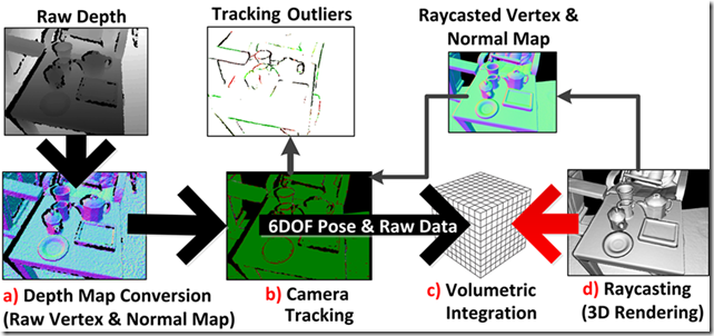
下图是从Kinect Fusion的处理流程。
- 第一步是深度影像数据的转换。SDK将Kinect中获取的原始深度帧数据转换为以米为单位的浮点数据,紧接着对该数据进行优化,通过获取摄像头的坐标信息,将这些浮点数据转换为和Kinect摄像头朝向一致的点云数据。这些点的表面情况通过使用AlignPointClouds函数获取。
- 第二步是计算全局的摄像头的姿势信息,包括摄像头的位置和朝向,通过使用交互型的配准算法在摄像头移动时不断获取其姿势,这样系统始终知道当前摄像头相对于起始帧时摄像头的相对姿势。Kinect Fusion中有两种配准算法。第一种叫NuiFusionAlignPointClouds,他用来将从重建对象计算得来的点云与从Kinect深度影像数据中获取的点云进行配准。或者单独的使用比如对同一场景的不同视场角的数据进行配准;第二种叫AlignDepthToReconstruction,该算法在对重建立方体进行处理时能够获得更高精度的追踪结果。但是对于场景内移动的物体该算法可能不够健壮。如果场景中的追踪被中断,那么需要将摄像头的位置和上一次的摄像头位置对齐才能继续进行追踪。
- 第三步是将从已知姿势摄像头产生的深度影像数据融合为代表摄像头视野范围内的景物的立方体。这种对深度数据的融合是逐帧,连续进行的,同时通过平滑算法进行了去噪,也处理了某些场景内的动态变化,比如场景内添加或者移除了小的物体等。随着传感器的移动从不同的视场角度观察物体表面。原始影像中没有表现出来的任何隔断或者空也会被填充,随着摄像头更接近物体,通过使用新的更高精度的数据,物体表面会被持续优化
- 最后,从传感器视点位置对重建立方体进行光线投射,重建的点阵云能够产生渲染了的三维重建立方体。
Kinect Fusion对物体的追踪仅仅使用Kinect 传感器产生的深度数据流。这种追踪主要依赖深度影像数据中不同位置深度数据有足够的深度差异。因此它能够将看到的数据融合起来以及计算传感器的不同位置差异。如果将Kinect对准一个平整的墙面或者又很少起伏变化的物体,那么追踪可能不会成功。场景中物体分散时效果最好,所以在使用Kinect Fusion对场景进行追踪时如果出现追踪失败的情况,不防试着对场景内的物体进行追踪。
Kinect Fusion中的追踪有两种算法,他们分别通过AlignDepthFloatToReconstruction和 AlignPointClouds 函数实现,他们都可以用于摄像头位置的追踪,但是,如果我们使用AlignDepthFloatToReconstruction 函数来创建一个重建立方体,可能会有更好的追踪精度。相比,AlignPointClouds 方法可以用于单独的,不需要重建立方体就可以将两个点云进行对齐。
三 相关API
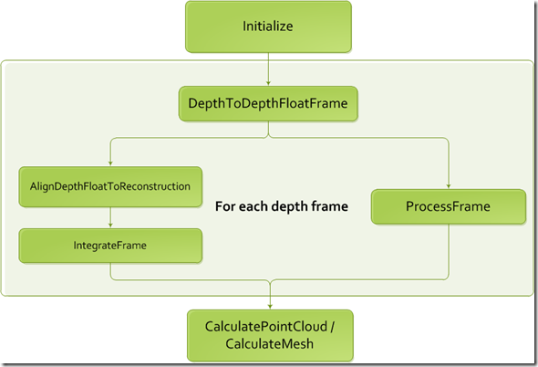
前面讲解了Kinect Fusion的工作原理,通过SDK中的相关API,我们可以使用Kinect Fusion来对真是场景进行三维重建,下图是Kinect Fusion相关的处理流程:
首先,需要进行初始化,在初始化阶段,Kinect Fusion会确定建模过程中的世界坐标系,并会构造一个带扫描的真实场景的静态的虚拟的立方体,在建模过程中,我们只关心在该虚拟立方体中的真实场景。
紧接着第一步是对每一帧深度影像数据进行如上图所示的处理。下面就简单介绍下上图中涉及Kinect Fusion的相关函数。
DepthToDepthFloatFrame 函数
该函数的签名如下:
|
1 |
public void DepthToDepthFloatFrame(DepthImagePixel[] depthImageData, FusionFloatImageFrame depthFloatFrame,float minDepthClip, float maxDepthClip, bool mirrorDepth) |
该方法将无符号短型深度影像数据帧格式转换为浮点型深度影像数据桢格式,它代表物体距离Kinect传感器的距离,处理好的数据存储在预分配的depthFloatFrame中,参数中depthImageData 和 depthFloatFrame 的大小必须一致,该函数在GPU上运行。
depthImageData 是从Kinect传感器获取的深度影像原始数据。minDepthClip 表示最小深度阈值,小于该值得都会设置为0,maxDepthClip 为最大深度阈值,大于该值得都被设置为1000,最后一个布尔型的mirrorDepth表示是否对深度数据进行镜像处理。
最小最大深度阈值可以用来对输入的数据进行处理,比如说可以排除某些特殊的物体,将这些物体排除在三维重建之外。
ProcessFrame 函数
接下来可以调用ProcessFrame函数,该函数在内部其实是先后调用了AlignDepthFloatToReconstruction 和 IntegrateFrame 这两个函数,这里先介绍ProcessFrame函数。
|
1 |
public bool ProcessFrame(FusionFloatImageFrame depthFloatFrame, int maxAlignIterationCount, int maxIntegrationWeight,Matrix4 worldToCameraTransform) |
该函数用来对每一帧经过DepthToDepthFloatFrame处理后的深度影像数据进行进一步处理。如果在AlignDepthFloatToReconstruction阶段追踪产生错误,那么接下来的IntegrateFrame阶段就不会进行处理,相机的姿势也保持不变。该函数支持的最大图像分辨率为640*480。
maxAlignIterationCount参数为配准过程中的迭代次数,该参数用来表示对齐相机追踪算法的迭代次数,最小值为1,值越小的计算速度更快,但是设置过小会导致配准过程不收敛,从而得不到正确的转换。
maxIntegrationWeight 参数用来控制深度影像融合的平滑参数,值过小会使得的图像具有更多的噪点,但是物体的移动显示的更快,消失的也更快,因此比较适合动态场景建模。大的值使得物体融合的更慢,但是会保有更多的细节,噪点更少。
WorldToCameralTransoform,参数为最新的相机位置。
如果该方法返回true,则表示处理成功,如果返回false,则表示算法在对深度影像数据对齐的时候遇到问题,不能够计算出正确的变换。
我们一般的可以分别调用AlignDepthFloatToReconstruction 和 IntegrateFrame 这两个函数,从而可以对更多的细节进行控制,但是,ProcessFrame速度可能更快,该方法处理成功之后,如果需要输出重构图像,则只需要调用CalculatePointCloud方法,然后调用FusionDepthProcessor.ShadePointCloud即可。
AlignDepthFloatToReconstruction 函数
|
1 |
public bool AlignDepthFloatToReconstruction(FusionFloatImageFrame depthFloatFrame,int maxAlignIterationCount,FusionFloatImageFrame deltaFromReferenceFrame, out float alignmentEnergy, Matrix4 worldToCameraTransform) |
该方法用来将深度影像数据桢匹配到重构立方体空间,并由此计算出当前深度数据帧的摄像头的空间相对位置。相机追踪算法需要重构立方体,如果追踪成功,会更新相机的内部位置。该方法支持的最大分辨率为 640*480。
maxAlignIterationCount 参数和ProcessFrame方法中的参数含义相同。
deltaFromReferenceFrame 表示配准误差数据桢, 是一个预先分配的浮点影像帧,通常存储每一个观测到的像素与之前的参考影像帧的对齐程度。通常可以用来产生彩色渲染或者用来作为其他视觉处理算法的参数,比如对象分割算法的参数。这些残差值被归一化到-1 ~1 的范围内,代表每一个像素的配准误差程度。如果合法的深度值存在,但是没有重构立方体,那么该值就为0 表示完美的对齐到重构立方体上了。如果深度值不合法,就为返回1。如果不需要这个返回信息,直接传入null即可。
alignmentEnergy 表示配准精确程度 ,0表示完美匹配
worldToCameraTransform 表示此刻计算得到的相机位置,通常该变量通过调用FusionDepthProcessor.AlignPointClouds 或者 AlignDepthFloatToReconstruction这两个方法获得。
该函数如果返回true则表示对齐成功,返回false表示则表示算法在对深度影像数据对齐的时候遇到问题,不能够计算出正确的变换。
IntegrateFrame 函数
|
1 |
public void IntegrateFrame(FusionFloatImageFrame depthFloatFrame,int maxIntegrationWeight, Matrix4 worldToCameraTransform) |
用于融合深度数据桢到重构场景中maxIntegrationWeight,控制融合的平滑程度 。
worldToCameraTransform 表示此时深度数据帧的相机位置,他可以由配准API计算返回。
CalculatePointCloud 函数
|
1 |
public void CalculatePointCloud(FusionPointCloudImageFrame pointCloudFrame,Matrix4 worldToCameraTransform) |
通过光线跟踪算法计算出某视点下的点云数据。
这些点云信息可以被用作 FusionDepthProcessor.AlignPointClouds或者FusionDepthProcessor.ShadePointCloud函数的参数。从而来产生可视化的图像输出。
pointCloudFrame参数是一个固定的图像大小,比如说,你可以窗体大小范围内的点云数据,然后放置一个image控件,通过调用FusionDepthProcessor.ShadePointCloud来填充这个image控件,但是需要注意的是,图像越大,计算所耗费的资源就越多。
pointCloudFrame 参数是一个预先分配的点云数据桢,他会被通过对重建立方体进行光线投射得到的点云数据进行填充,通常通过调用FusionDepthProcessor.AlignPointClouds 或者FusionDepthProcessor.ShadePointCloud.函数产生。
worldToCameraTransform参数表示相机视点的位置,用来表示光线投射的位置。
CalculateMesh 函数
|
1 |
public Mesh CalculateMesh(int voxelStep) |
用于返回重构场景的几何网络模型。该函数从重建立方体输出一个多边形立体表面模型。voxelStep 描述了采样步长,采样步长设置的越小,返回的模型就越精致。
四 结语
理解了这几个函数,那么就应该差不多能够使用Kinect Fusion提供的功能了,最好的学习方式就是直接查看Kinect Developer Toolkit中提供的示例程序的代码,相信理解了上面的函数,看起来应该不会太吃力。
由于本人笔记本配置达不到要求,所以没有办法演示,不过相信通过上面的介绍,对您了解和使用Kinect Fusion应该会有所帮助。
Some Technical Details about KinectFusion
KinectFusion is a powerful 3D reconstruction technique based on Microsoft Kinect Sensor. It’s included in the Microsoft Kinect SDK, which is pretty easy to use. But if you wish to do some serious vision applications based on that, more technical details need to be figured out. And here are some notes I took these days.
WorldToCamera matrix
Just as the name indicates, it’s just the external parameter matrix of the camera (i.e. Kinect here), consisting of the rotation and the translation info. You can get it from the GetCurrentWorldToCameraTransform() function in the SDK. More specifically, the matrix looks like
And to transform a 3D point in the global coordinates to the local 3D coordinates of the camera, one only needs to do
⎡⎣⎢⎢xlylzl1⎤⎦⎥⎥=[R0t1]∗⎡⎣⎢⎢⎢xgygzg1⎤⎦⎥⎥⎥.
From the code it’s also easy to know the (inverse of the) internal matrix of the Kinect (optical) camera (when the resolution is 640×480).
F−1=⎡⎣⎢594.21591.04320/594.21240/591.041⎤⎦⎥,
then the (homogeneous) coordinates of the point can be computed as
⎡⎣uv1⎤⎦=F−1⎡⎣⎢xl/zlyl/zl1⎤⎦⎥
To verify the correctness of your implementation, simple export two RGBD photos with WorldToCamera matrices, manually label the same 3D point on the two depth photos, and see whether they get transformed to the same 3D coordinate.
RGB-depth alignment
In the previous verification experiment, the reason why we don’t use optical photos to label is, direct export from Kinect SDK ends up with unaligned optical and depth photos. That is, since the optical camera and the depth camera are not in the position (and have different view of angles), their photos are not aligned, or the depth in (u, v) in the depth photo is not the “depth” for the pixel at (u, v) in the optical photo. To build applications involving both photos, you need to first align them, or in other words, warp the optical photo to fit the depth photo (or vice versa).
It can be done with the SDK itself, with the function CoordinateMapper.MapDepthFrameToColorFrame(). Since there are detailed documents in MSDN, I’d save time here by leaving yourself read the documents. But the MATLAB code is provided here.
Some assumption to use the code is, the file imgfn stores the binary data directly exported fromColorImageFrame.CopyPixelDataTo(), dfn stores the binary data exported from FusionFloatImageFrame.CopyPixelDataTo(), and idxfn stores the binary data exported from the ColorImagePoints resulted fromCoordinateMapper.MapDepthFrameToColorFrame().
Example exporting code would look like this:
|
1 2 3 4 5 6 7 8 9 10 |
var colorImagePoints = new ColorImagePoint[depthPixels.Length]; mapper.MapDepthFrameToColorFrame(DepthImageResolution, depthPixels, ColorImageFormat.RgbResolution640x480Fps30, colorImagePoints); File.WriteAllBytes(string.Format("{0}_coloridx.dat", fn), colorImagePoints.SelectMany(x => { var result = new List<byte>(); result.AddRange(BitConverter.GetBytes(x.X)); result.AddRange(BitConverter.GetBytes(x.Y)); return result.ToArray(); }).ToArray()); |
With such alignment or rectification, we can repeat the experiment introduced in the last section with the optical photos now.
WorldToVolume matrix
The WorldToVolume matrix is pretty like WorldToCamera matrix, mapping the world coordinates to volume coordinates. The comment in the SDK basically illustrate how the volume coordinate works, and it’s as easy to use as the WorldToVolume matrix,
⎡⎣⎢⎢xvyvzv1⎤⎦⎥⎥=[R0t1]∗⎡⎣⎢⎢⎢xgygzg1⎤⎦⎥⎥⎥.
Note the t in the matrix may be negative, because it’s not necessary to store info too close to the camera. And since the comment in the code mentions that the origin of the world coordinate system lies in the center of the front plane (i.e. z == 0 plane) in the volume, you may want to assign at least 2t space for the volume.
Raycasting for better depth
A smart way to use the KinectFusion is to extract depth map with better quality from the volume, rather than directly fetch it from the sensor. Since the Truncated Signed Distance Function smoothes the surfaces among frames it’s seen before, such extracted depth map would be more robust to sensor noise and missing values (which is a common problem for Kinect sensor).
To extract such depth map, we need to first export the point cloud stored in the volume with the functionCalculatePointCloud() (with the WorldToCamera matrix), and then map each 3D point to the camera imaging plane based on the external as well as internal matrices of the camera.
Here are some results to give you a sense.


 小明编程
小明编程


![[转]matlab自带相机标定程序对kinect进行简单标定-小明编程](https://ws1.sinaimg.cn/large/005HYjuQly1fijj7qtsu3j30c207dq5o.jpg)


![[转]利用Kinect把任意屏幕变得可触控-小明编程](https://brightguo.com/wp-content/uploads/2017/04/o_wite-220x150.png)
![[转]深度图像的获取原理-小明编程](https://brightguo.com/wp-content/uploads/2017/04/20170406100208362-220x150.png)


